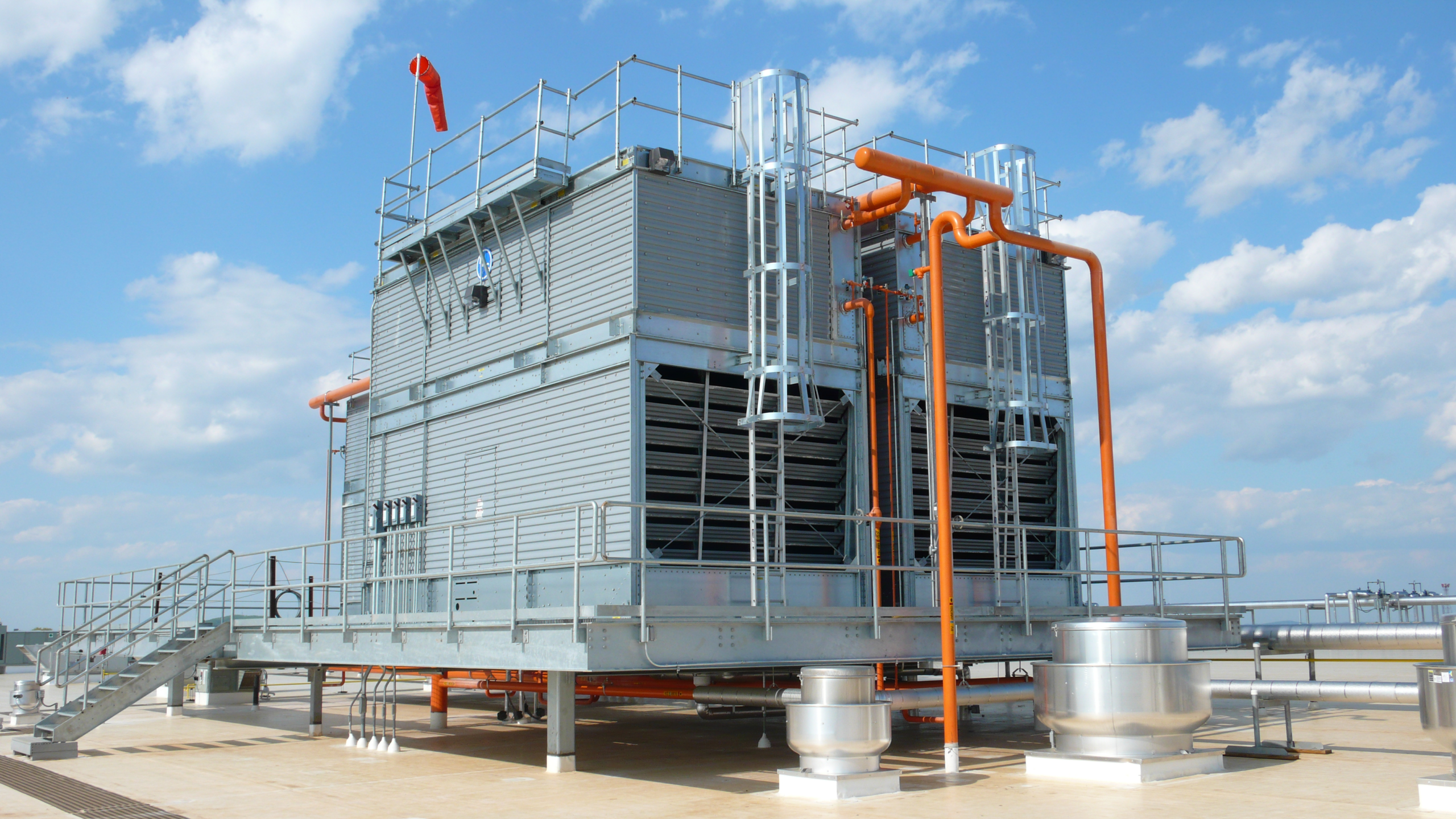
Baltimore Aircoil Company has published a new technical manual for evaporative condenser piping, bringing together design guidance for industrial refrigeration systems with a particular focus on ammonia installations.
The Evaporative Condenser Piping Manual covers discharge piping, condenser drain lines, liquid drop leg sizing, thermosiphon circuits, equalisation, purge arrangements and hydrostatic overpressure protection. BAC says the guidance combines engineering practice with field experience and recommendations derived from laboratory testing.
An evaporative condenser removes heat from refrigerant leaving the compressor. Hot high pressure vapour enters the condenser coil, heat passes through the tube wall to air and evaporating water, and the refrigerant changes state into high pressure liquid before flowing towards the receiver.
Pipework downstream of the coil determines whether that liquid can leave the condenser at the rate the refrigeration system requires. Diameter, elevation, pressure loss and receiver arrangement all influence the available driving head, so a correctly selected condenser can still perform poorly if its discharge piping restricts drainage.
Liquid backing up inside the condenser occupies coil volume that should be available for condensing vapour. The effective heat transfer area falls, condensing pressure can rise and the compressor has to work against a higher discharge pressure, increasing electrical demand even when the condenser fans, pumps and heat transfer surfaces themselves remain mechanically sound.
BAC gives particular attention to liquid drop legs, which provide the vertical liquid column used to overcome pressure differences between the condenser outlet and the high pressure receiver. Required height depends on the operating pressure relationship and piping configuration rather than being a dimension that can be selected independently of the rest of the system.
Insufficient liquid head can restrict drainage and allow refrigerant to accumulate in the condenser. Excessively large or poorly arranged piping can create different problems, including greater refrigerant inventory and unstable behaviour as load changes.
Pipe diameter also affects refrigerant velocity and pressure loss. Drain lines have to carry the expected liquid flow without creating enough resistance to undermine the available head, while their geometry must account for vapour and liquid occupying the system under different operating conditions.
Multiple condenser installations add another hydraulic interaction because each unit has to drain into a common system without one condenser imposing unfavourable pressure conditions on another. Differences in elevation, branch resistance or operating state can produce unequal drainage unless the piping maintains the required pressure balance.
BAC includes arrangements for single and multiple condenser systems and addresses equaliser piping between the relevant vessels and connection points. Equalisation allows pressure to communicate where needed so liquid can move by gravity instead of becoming trapped by an unintended pressure difference elsewhere in the circuit.
The manual also covers open channel flow in condenser drain headers and the use of P-traps. A drain line does not necessarily run completely full of liquid under every operating condition, so treating it as a conventional pumped liquid pipe can produce incorrect assumptions about velocity, pressure drop and available drainage capacity.
Thermosiphon cooling creates another demand on the high pressure liquid system. Industrial ammonia installations can circulate refrigerant through equipment such as compressor oil coolers using density differences rather than a dedicated mechanical pump, but that circulation depends on sufficient liquid head and a clear return path.
Condenser, receiver and thermosiphon arrangements have to operate together. Liquid level, line resistance, venting and elevation all influence whether enough refrigerant reaches the cooling load and returns without disturbing condenser drainage.
BAC provides separate liquid drop leg sizing guidance for systems with and without thermosiphon cooling. Using the same piping assumptions for both can leave an installation apparently correct on a static drawing but unable to maintain stable refrigerant movement across its operating range.
System charge is affected by the same design choices. Larger pipes and arrangements that retain unnecessary liquid increase the amount of refrigerant required to fill the installation. In ammonia systems, reducing avoidable inventory can lower both material cost and the quantity of hazardous refrigerant on site, provided operating stability is preserved.
Noncondensable gases reduce performance through a different mechanism. Air and other gases entering the refrigeration circuit do not condense with the ammonia at normal operating conditions, so they occupy condenser volume and can increase head pressure if they accumulate.
Purge piping arrangements remove those gases under controlled conditions. Ammonia handling introduces safety and environmental requirements, so purge, maintenance and refrigerant recovery procedures still have to comply with applicable legislation and established industry practice.
Hydrostatic overpressure becomes possible wherever liquid refrigerant can be trapped between closed valves. A temperature rise causes the liquid to expand, but a completely filled section of pipe offers almost no free volume into which that expansion can occur, allowing pressure to rise rapidly.
Relief or equivalent protection has to be provided wherever the operating arrangement can isolate liquid. Those conditions may occur during shutdown, maintenance or valve operation rather than normal production, making them easy to miss when a design is reviewed only around the expected flow path.
Mechanical support forms another part of BAC’s guidance because refrigerant piping loads the structure as well as the process. Pipe weight changes with refrigerant inventory, while wind, seismic forces, thermal expansion and equipment movement can transmit additional loads into supports and condenser connections.
Local codes and International Institute of Ammonia Refrigeration recommendations remain part of the design basis, so the manual does not replace project specific engineering. It consolidates the condenser related hydraulic and mechanical considerations that need to be resolved before an installation is commissioned.
Many piping faults still allow a refrigeration plant to start and operate, leaving poor drainage or excessive charge hidden behind higher energy use, unstable liquid levels and intermittent control problems. Correcting those conditions after commissioning can require pipework modifications around equipment that is already in service.
Treating the condenser, receiver, drain lines, equalisation and thermosiphon circuits as one pressure and flow system gives designers a better chance of avoiding those corrections. Applying the relationships during design can prevent elevated head pressure and unreliable liquid movement from becoming operating problems that are discovered only after the plant is running.