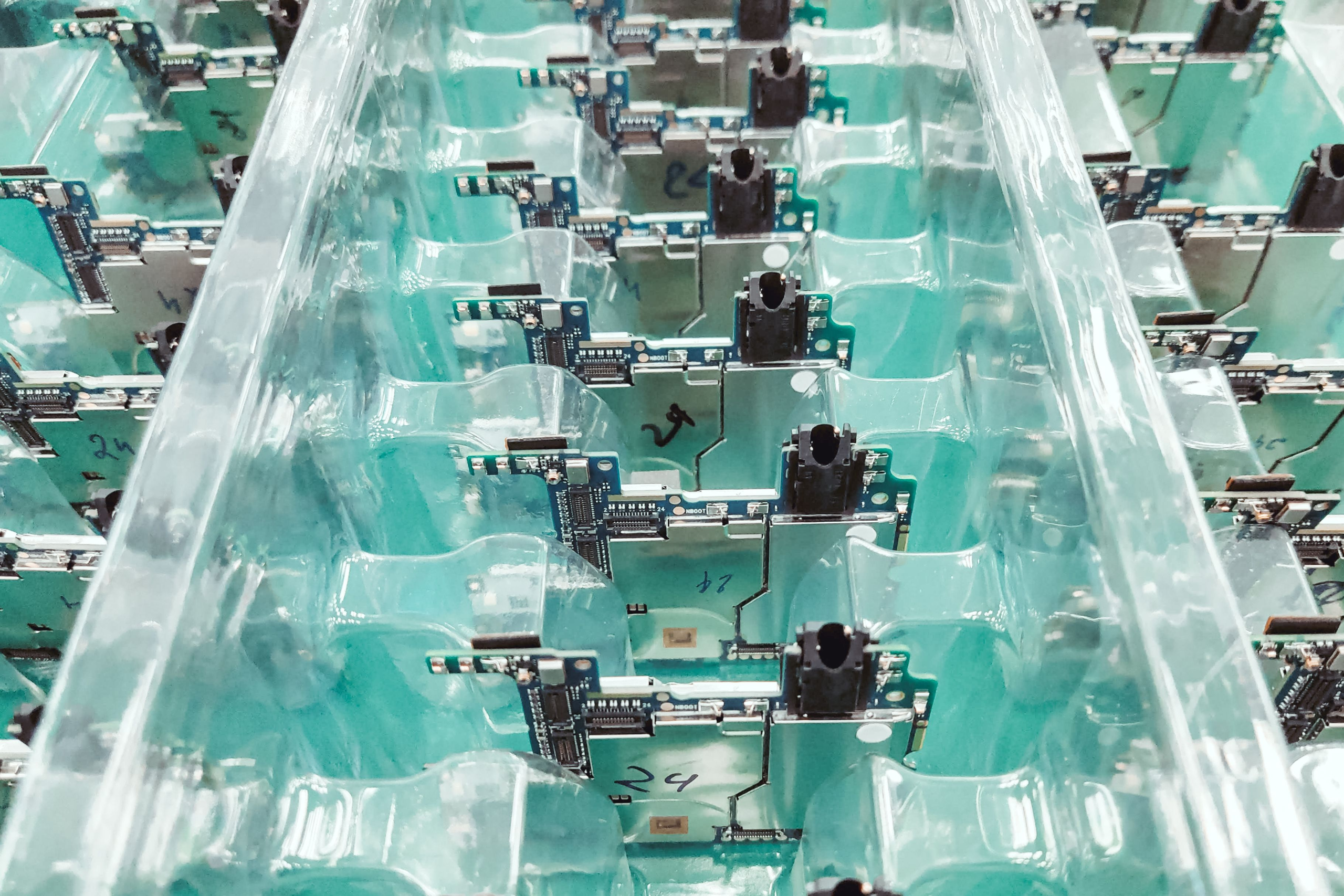
Infineon Technologies has introduced a high-voltage hot-swap controller designed to protect power distribution paths in future AI server racks using 800V or split ±400V direct-current architectures. The XDP8HD40S-1 combines digitally controlled startup behaviour, programmable electrical protection and remote diagnostics, allowing designers to manage the connection and disconnection of demanding server loads without relying solely on external discrete control circuitry.
As computing racks draw more power, higher distribution voltage can reduce current for a given transmitted load and ease some conductor losses. It also raises the demands on insulation, switching, fault detection and isolation within the power path. The XDP8HD40S-1 is a proposed component for that architecture; system-level operating results will depend on the converters, external switches and protection design selected by equipment manufacturers.
Hot swapping allows a subsystem to be connected or disconnected while a wider electrical installation remains energised. At high DC voltage, that is a demanding switching problem: the capacitors inside a newly connected load can draw a large charging current, while a fault may force a power switch to interrupt current before other circuits are affected. A controller has to regulate the initial current, assess voltage and temperature conditions and command the external power device to switch off when predefined limits are exceeded.
Inrush control is especially important when high-capacity power modules, converters or server subsystems are connected to a common bus. The energy required to charge input capacitors can impose significant temporary stress on a switching element. Excessive current, prolonged operation in a partially conducting state or uncontrolled transients may damage the device. Infineon addresses this with digital Safe Operating Area control, which seeks to keep the controlled power switch within specified combinations of voltage, current and operating time during startup.
The XDP8HD40S-1 also incorporates a variable pulse Safe Operating Area mode, described by Infineon as Boost Mode, to adjust startup behaviour. It adds programmable active protection for abnormal input and output voltage, overcurrent and excess temperature, together with surge immunity. These functions give engineers options for defining the appropriate response to faults, but they do not remove the need to coordinate settings with the actual power stages, thermal design and upstream protective equipment.
An integrated gate driver supports external silicon carbide cascode arrangements combining a MOSFET and JFET. This is a circuit-level choice for controlling the high-voltage switching stage rather than a claim that the controller itself carries an entire rack’s load current. Infineon specifies a configurable pull-down current of up to 1.5A to turn the external switch off rapidly under abnormal conditions. The effectiveness of shutdown will still depend on the complete circuit, parasitic inductance, device selection and fault conditions.
A PMBus 1.5 management interface allows the controller to report electrical status and diagnostic information to supervisory equipment. Its black-box function records selected information about critical events that may help engineers investigate a trip. Such records must be correlated with external sensing, upstream protection and system logs, rather than taken as a complete explanation of a shutdown. Configuration and access controls also influence the usefulness of a remotely managed protection stage.
The component is intended for applications including two-wire 800V distribution, split ±400V configurations, intermediate bus converters, battery backup arrangements and high-voltage server power paths. The choice between these architectures influences insulation design, connector ratings, fault isolation and maintenance procedures. A topology suitable for one rack or conversion stage is not automatically transferable to another, especially when the operating voltage, grounding arrangement and available fault energy differ.
Higher distribution voltage can reduce current for a given transmitted power, potentially lowering resistive losses and conductor requirements. It also increases the engineering burden associated with insulation, creepage and clearance, connectors and fault management. DC systems require particular attention to interruption behaviour because they lack the natural current zero crossing present in alternating-current waveforms. A hot-swap controller is one protective layer within that wider electrical design, not a substitute for the rack’s complete safety and protection architecture.
Infineon lists supply ranges for the controller’s internal operating domains and specifies a 40-pin LFDSO package measuring 10.7 by 10.3 millimetres. The electrical and thermal interfaces of that package will have to be assessed alongside the external switching devices and PCB layout. The manufacturer’s published specifications describe component-level capabilities, not the system test results needed to substantiate fault tolerance for an assembled rack.
During a high-voltage fault, the time needed to recognise abnormal current and turn off the external switch influences the stress imposed on conductors and other equipment. Wiring inductance, the energy stored in capacitors and the coordination of upstream protection may all alter the response observed in a finished installation. Those conditions must be evaluated during system qualification, independently of the controller’s programmable protection settings.
Samples of the XDP8HD40S-1 are targeted for the second quarter of 2027. Engineers will then be able to test startup and shutdown behaviour, diagnostic communications and fault coordination within prospective 800V or split ±400V designs. Rack-level qualification and operating evidence will be required before claims of improved uptime or reliable deployment can be substantiated.